
KTE - 7000SB
SOLAR WATER HEATING & BOILER EXPERIMENTAL EQUIPMENT

Equipment Introduction
The Solar Thermal Boiler Training System (KTE-7000SB) is designed to support understanding of solar heat collectors, heat storage, and heat control systems.
It enables comparative testing and practical experiments by calculating thermal energy under different load conditions using three types of loads.
The system allows performance testing of a solar thermal boiler using both artificial sunlight and natural sunlight, and provides education on the structure and operating principles of solar thermal boiler systems.
Users can conduct experiments by collecting natural sunlight after installing the solar heat collector outdoors, and gain hands-on experience in system control through integrated control systems.
Equipment characteristics
Enables radiant energy experiments using artificial (halogen) light sources or natural sunlight
Allows calculation of heat collection rate and measurement of system efficiency
The load modules are detachable, enabling easy connection of alternative loads to the main system
Supports operation with separated load and boiler sections, allowing flexible use of different load configurations
Enables measurement of temperature at multiple points, including the solar collector, heat storage unit, and load sections
Supports real-time monitoring and data storage during performance testing
Provides understanding of the operating principles of solar thermal hot water boiler systems
Enables automatic control training for solar thermal systems
Supports load rate calculation practice for various types of heat exchangers
Education Contents
Measurement and analysis of solar thermal hot water boiler systems using software
Configuration of solar thermal hot water boiler systems, including performance measurement and analysis
Configuration and operation of temperature-controlled heat storage tank sequence control circuits
Configuration and operation of differential control circuits for heat collection circulation pumps
Configuration and operation of heat storage and heat emission switching circuits using three-way valves
Configuration and operation of heat collection medium switching sequence control circuits
Configuration and operation of heat transfer medium charging control circuits for heat storage tanks
Configuration and operation of auxiliary heater sequence control circuits for solar thermal hot water boiler systems
System Description

Components of the Equipment

Control Panel Device Component

Structure of DA100 Program

(1) System schematic diagram
Schematic diagram of the solar thermal hot water boiler system
(2) Performance graph display
Graphical display of system performance data over time
(3) Measurement data table
Tabulated display of temperature, pressure, and enthalpy data
(4) Performance calculation results
Calculation and display of performance values such as heat collection rate, cooling capacity, and heating capacity
Function
Real-time monitoring of collector, heat storage tank, and load temperatures using dedicated PC software
For solar heating systems, users can manually input the specific heat capacity (Cp), which is then applied to performance calculation formulas
Supports multiple heat transfer media, including:
Water
Water + Propylene Glycol (PG)
Water + Ethylene Glycol (EG)
Allows users to select the data acquisition interval within the software
Provides graph plotting of temperature and thermal energy values
Automatically sets the Excel file name at program startup and continuously saves data to prevent data loss caused by unexpected events such as power outages or program shutdowns
Supports real-time monitoring of battery consumption conditions
Includes a system flow diagram to enhance understanding of equipment operation
Allows the flow diagram to be saved as a JPG file
Generates graphs using user-selected real-time data for analysis and comparison

Operation Principles of Active Solar System
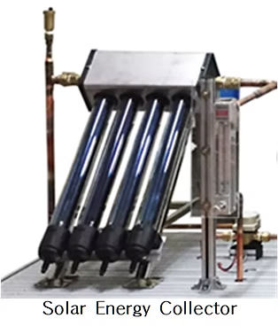
Heat Collecting Process
Solar heat energy is received from the sun.
The temperature inside the solar heat collector increases.
Pump 1 and Pump 2 start operating.
The heat collecting medium enters T2 (collector inlet), flows through T14, where it absorbs solar energy, and exits through T3 (collector outlet).
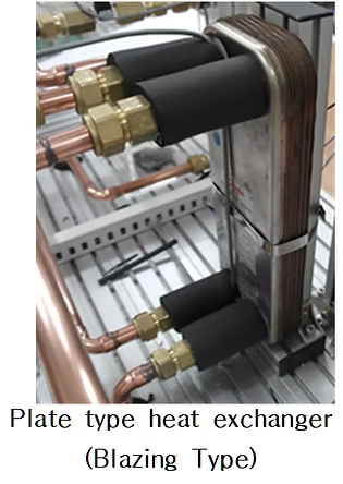
The heated medium then enters the heat exchanger, where thermal energy is transferred to the heat storage medium through heat exchange.
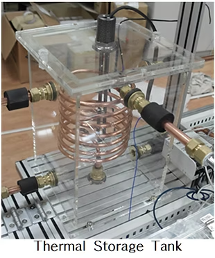
Heat Storing Process
Pump 1 (heat collecting circulation pump) operates in conjunction with Pump 2.
The thermal medium stored in the heat storage tank flows from T5 (tank outlet), passes through the heat exchanger, and enters T4 (tank inlet).
During this process, heat energy is transferred from the heat collecting medium to the storage medium and accumulated in the upper section of the heat storage tank.
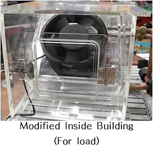
Heat Processing (Heat Utilization Process)
When the internal chamber temperature T13 is lower than the preset value,
Pump 3 starts operating.
The thermal medium stored in the heat storage tank passes through a distributor and flows into T8 (or T10).
The medium transfers heat to the chamber through the heat exchanger, and then returns to the heat storage tank via T9 (or T11).
Video Clips for Product Usage
